
Making a circuit with a microcontroller, battery, and LEDs connected by copper tape.
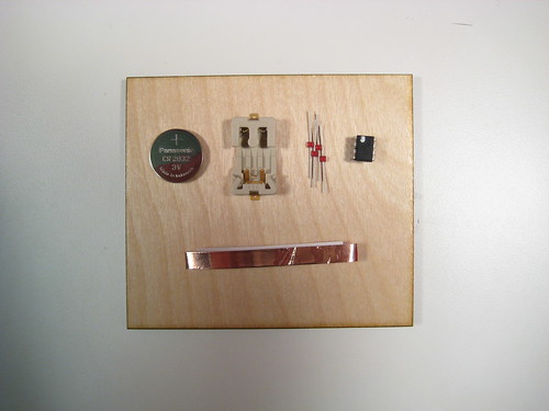
Components (for more, see our electronic components page):
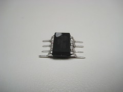
- ATtiny85V microcontroller, 8-pin DIP package (or the ATtiny45V)
You’ll need to program these before using them; see below for details. - Red Axial LED (or Green or yellow)
- CR2032 Coin Cell Battery Holder
- CR2032 Coin Cell Battery
- Copper Tape (1/4″)
- A piece of scrap wood, paper, or other non-conductive flat material.
Tools:
- Hot glue gun
- Soldering iron
Programming the Microcontroller
Note that you’ll need to program the microcontroller before using it. See this tutorial for more information.
Download: touch.zip (the Arduino program to load onto the microcontroller)
Understanding the Components
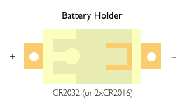
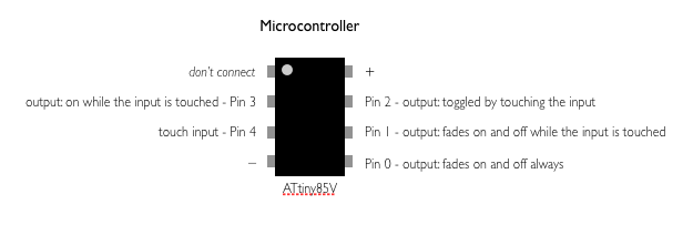
Each of the components has multiple legs and it’s important to connect them correctly. Below are diagrams of each components, with labels indicating the behavior of each lead.
The battery holder has + and – terminals (which are also marked on the holder itself). They are also known as power (+) and ground (-). The LED has + and – leads. You can tell which is which by looking for the silver stripe on the bottom of the LED; it marks the – lead.
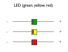
The microcontroller has multiple pins. Two are + and -, which provide power to the microcontroller. One pin is an input; the microcontroller can tell when you touch that pin and the ground pin with your finger. The other pins are outputs; you can connect LEDs to them. The behavior of each LED is different and is described in the diagram.
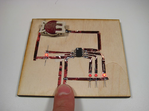
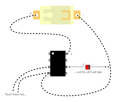
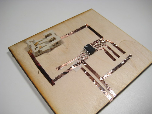
Example Circuit
Here’s an example circuit showing the connections between the components. Here, we’ve connected the + leg of the LED to one of the outputs of the microcontroller (the one that fades when you touch the microcontroller’s input and ground). We could also connect other LEDs to the other legs of the microcontroller.
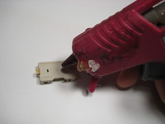
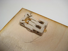
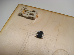
Hot-Gluing the Components to the Wood
Hot glue the battery holder and the microcontroller to the wood (or other material). Spread the legs of the microcontroller flat first. You might want to sketch out your circuit with pencil (either before or after gluing down the components).
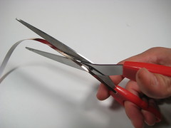
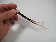
Preparing the Copper Tape
You’ll want to cut the tape in half to make thinner strips. For the pieces that go to the legs of the microcontroller, you might want to cut the tape even thinner.
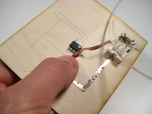
Making Connections with Copper Tape
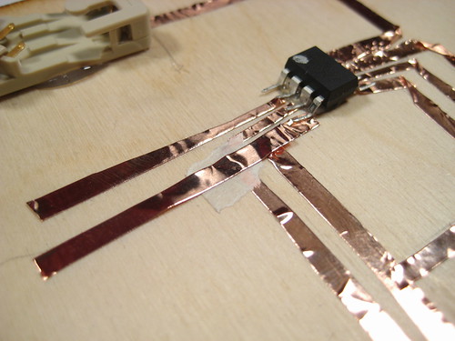
Lay down strips of copper tape to make your circuit’s connections. Try to slip the tape under the legs of the components so it’s easier to solder them together later. In general, it’s better to use a single piece of tape for a connection, folding it at corners – multiple pieces of tape will probably need to be soldered together to work.
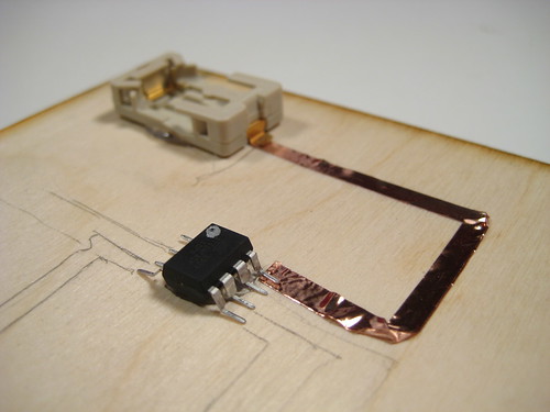
Connecting the Rest of the Circuit
Connect the rest of your circuit with copper tape, leaving gaps for the LEDs you want to connect.
Make sure that the pieces of tape don’t touch each other, especially near the legs of the microcontroller.
If you need to jump a piece of copper tape over another one without creating an electrical connection between them, you can separate the two with a piece of masking tape.
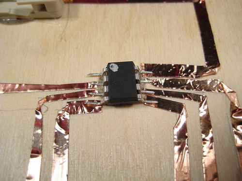
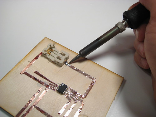
Soldering the Battery Holder and Microcontroller
Solder the legs of the battery and microcontroller to the copper tape. Also, if you have places where two pieces of copper tape meet (and should be electrically connected), solder them together at the intersection. Again, make sure you don’t solder together two legs of the microcontroller (or other things that shouldn’t be electrically connected).
Soldering the LEDs
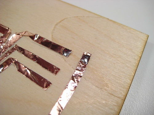
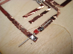
Melt dabs of solder onto the piece of copper tape on either side of where you’ll place an LED.
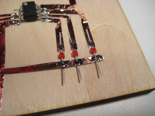
Solder the LED in place. Remember that the silver stripe on the back of the LED should go to ground.
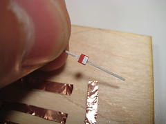
Repeat for the other LEDs in your circuit.
Testing your Circuit
Insert the battery. If you touch the input pin of the microcontroller and ground with your finger, the LEDs should react.
Troubleshooting
Some things to check if the circuit doesn’t work at first:
- Try another battery. The first one might have been dead.
- Make sure that all the connections are soldered, including places where two pieces of copper tape meet (if they’re supposed to be electrically connected).
- Make sure that there aren’t any places where two pieces of tape touch that shouldn’t be electrically connected.
- Make sure that you have + and – of the battery holder going to + and – of the microcontroller, respectively.
- Make sure your LEDs aren’t backwards (i.e. check that the silver stripe on the back of the LED goes to ground).