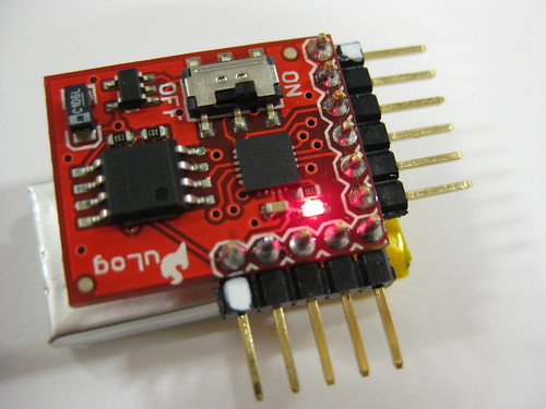
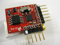
Sparkfun has a nice little module for logging up to three channels of sensor data for up to three hours and then spitting it out on command.
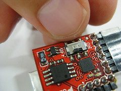
The uLog is an analog logging device that can log three channels of analog data (10 bit=1024 values) simultaneously for about 2 hours. It uses the ATtiny24 microcontroller with an AT45DB161D 16Mbit flash memory IC. It samples at 50Hz (=50 times a second).
- uLog runs on 3.3V (5V will kill it!!! Or at least I think this is what happened to my first board, and in the AT45DB161D datasheet is says “Single 2.5V – 3.6V or 2.7V – 3.6V Supply”)
- If connecting with a Sparkfun FT232 Basic 5V breakout board, you only want to connect TX, RX and ground and power seperately!!!
- If connecting with a Sparkfun FTDI Basic 3.3V breakout board you can power it from the the FTDI board directly
- When connecting/communicating with uLog to read/erase data use 38400 baudrate!!!
Type “r” for read and “e” for erase - Erasing the flash sets all addresses to 0xFFFF, and reading dumps all the data up to the first 0xFFFF
- If there’s no UART line attached it starts sampling from the sensor inputs (if no sensors are attached it will sample noise)
- Blinks at second intervals when reading sensor data (powered up and not connected to UART = rx,tx,gnd)
- Does not blink or light up at all when communicating over serial (powered up and connected to UART = rx,tx,gnd)
- Blinks like crazy when erasing data
If there is a UART line (rx, tx) attached when you switch on or power the uLog it spits out a “?” over the serial port and waits for user input. Sending an “r” over the serial port reads all the stored (logged) data in HEX values up until the first empty (0xFFFF) value.
Sending an “e” over the serial port erases all the memory and sets all addresses to 0xFFFF.
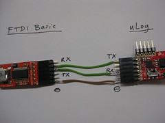
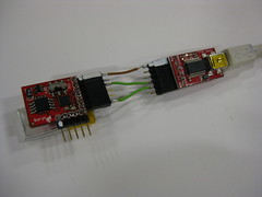
USB, connecting as follows:
FTDI —– uLog
+3.3V —– +3.3V
GND —– GND
RX —– TX
TX —– RX
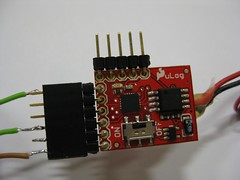
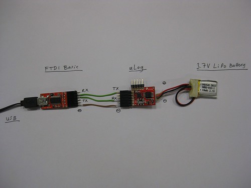
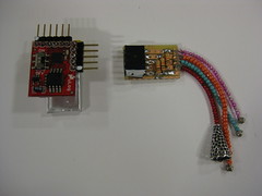
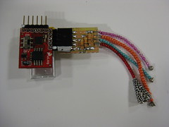
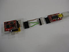
If your FTDI board is 5V you’ll need to power the uLog separately, either with the power supply you use for reading sensor data or using a volatage regular to power down the USB 5V. Still connect the GND from the FTDI to the uLog, connecting as follows (as seen in photos):
FTDI —– uLog
GND —– GND
RX —– TX
TX —– RX
uLog —– 3.3V power supply
+3.3V —– +3.3V
GND —– GND
Sparkfun uLog >> http://www.sparkfun.com/commerce/product_info.php?products_id=9228
Sparkfun FTDI Basic Breakout – 3.3V (5V also possible) >> http://www.sparkfun.com/commerce/product_info.php?products_id=8772
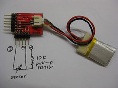
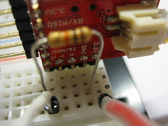
Setup for writing sensor data to memory from one (Z) analog input

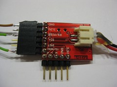
Setup for reading sensor data from memory via USB to serial port of computer
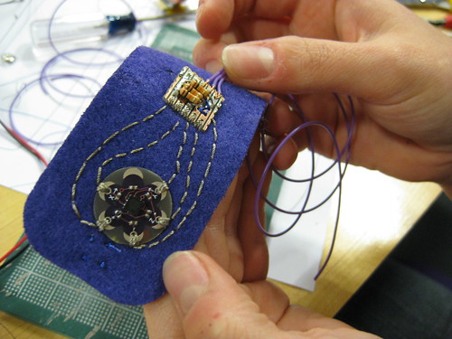
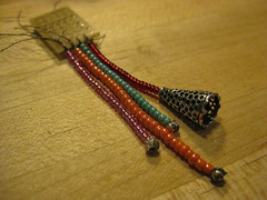
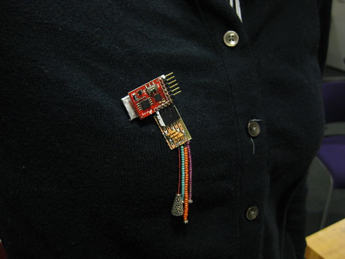
Example: Logging Wearable Sensor Data
Using Sparkfun’s uLog datalogging module to log tilt data a three-way fabric tilt sensor for up to three hours and then visualizing this with the help of a Processing sketch.
LINKS
Data logging: http://www.kobakant.at/DIY/?p=2123\\
Sensor Sleeve example: http://www.kobakant.at/DIY/?p=2542\\
Sparkfun uLog: http://www.sparkfun.com/commerce/product_info.php?products_id=9228\\
Download processing sketch: http://web.media.mit.edu/~plusea/downloads/SockLogger_uLog.zip\\
Download arduino/lilypad sketch to read and send first 3 analog sensor inputs:\\
http://web.media.mit.edu/~plusea/downloads/SockLogger_Arduino.zip\\
Download processing sketch for real-time graph of first 3 analog sensor inputs:\\
http://web.media.mit.edu/~plusea/downloads/SockLogger_lily.zip
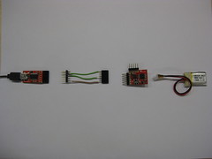
MATERIALS
* Sparkfun’s uLog – The Lil’est Logger (20$)
* Sparkfun’s Basic FTDI Breakout Board (15$)
* Male and female header connections
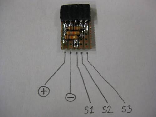
* Series of three 10 K Ohm pull-up resistors soldered to a piece of perforated circuit board
SOME FACTS
* uLog runs on 3.3V (5V will kill it!!! Or at least I think this is what happened to my first board, and in the AT45DB161D datasheet is says “Single 2.5V – 3.6V or 2.7V – 3.6V Supply”)
* If connecting with a Sparkfun FT232 Basic 5V breakout board, you only want to connect TX, RX and ground and power seperately!!!
* If connecting with a Sparkfun FTDI Basic 3.3V breakout board you can power it from the the FTDI board directly
* When connecting/communicating with uLog to read/erase data use 38400 baudrate!!!
* Type “r” for read and “e” for erase
* Erasing the flash sets all addresses to 0xFFFF, and reading dumps all the data up to the first 0xFFFF
* If there’s no UART line attached it starts sampling from the sensor inputs (if no sensors are attached it will sample noise)
* Blinks at second intervals when reading sensor data (powered up and not connected to UART = rx,tx,gnd)
* Does not blink or light up at all when communicating over serial (powered up and connected to UART = rx,tx,gnd)
* Blinks like crazy when erasing data
STEP 1)
Build your sensor! Connect it to the pull-up resistor board.
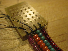
STEP 2)
Connect your sensor to the uLogger.
STEP 3)
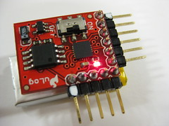
Turn on the uLog module and the red LED light should blink every second while it logs sensor data for up to 2 hours.
STEP 4)
Wear your sensor and log data for up to 2 hours.
STEP 5)
Turn off the uLog module and unplug your sensor.
STEP 6)
Pug the uLog into the FTDI board using the adaptor.
STEP 7)
Turn on the uLog while it is connected to the FTDI board and this is powered by a mini USB cable going to your laptop. This time the red LED will not blink, indicating that the uLog module is in serial communication mode.
STEP 8)
Run the Processing application by pressing the “play” button in the top left hand corder of the window. Type “r” to read sensor data, type “e” to erase the sensor data.
If you press “r”: The graph application will graph the incoming sensor values as they come in, and then zoom out to display them all in one graph.
If you press “e”: watch the uLog module as the red LED light blinks like crazy. Once it has stopped blinking you can disconnect it from the FTDI board and start recording new data.
Tayo’s Stepper Socks Example


Emily’s Accelerometer Bracelet Example