
Conductive traces can be painted in a variety of ways. When using a paintbrush it can be hard to apply the paint in narrow lines, which you sometimes want to do in order to paint right up close to the legs of a component that are tightly spaced (surface mount and through-hole standard spacings). Also, in particular with the copper paint, applying it with a paintbrush disperses the conductive particles so that you might have to apply multiple layers for the paint to be highly conductive. Instead of using a paintbrush you can also apply the paint through the nozzle of a squeeze bottle.
Silver paint is much more expensive than copper paint, but has some benefits. The silver particles in the water based silver paint WB-101 from conductive compounds are so fine that you can easily use a paintbrush or even fountain pen without worrying about conductivity. Because the paint is water based you can adjust its viscosity by adding water and mixing well. Of course you want to pay attention to your water:silver ratio so that your paint remains conductive.
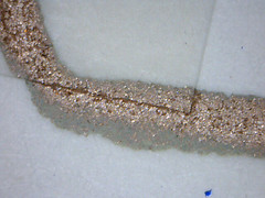
This tutorial describes the process of painting copper traces with a henna applicator squeeze bottle.
Copper squeeze-bottle traces
Step-by-step
This example introduces the use of conductive copper paint to paint electrical circuitry on paper. Working with surface mount and through-hole components. In the example we program the microcontroller to generate and play different sounds based on the value coming in to one of the analog inputs.
Materials and Tools
Basics:
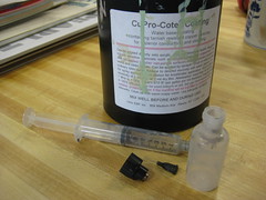
* conductive paint (copper or silver)
* resistive paint (carbon)
* paper (water color paper absorbs more liquid, the conductive paint will dry faster)
* the squeeze bottle is a henna applicator bottle
* nozzle for squeeze bottle
* syringe
* stickers for jumping traces
* pencil for sketching or drawing resistors
* mixing stick
* paint brush
Electrical Components:
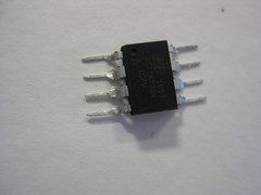
* Atmega ATtiny 85 through-hole (DIP) microcontroller
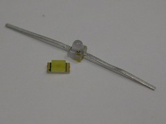
* surface mount LED
* 3V coin cell battery
Paper Battery Holder:
* foam
* double sided stickytape
* stapler and staples
Programming:
* AVRispmkII programmer
* alligator clips
* computer to program microcontroller
Facts
Paint is good for about a day (maximum one week) after you put it into the plastic applicator bottles. You can use a beading needle to clean out the syringe tip, but this is a losing battle if the paint is old.
Preparing conductive paint for painting
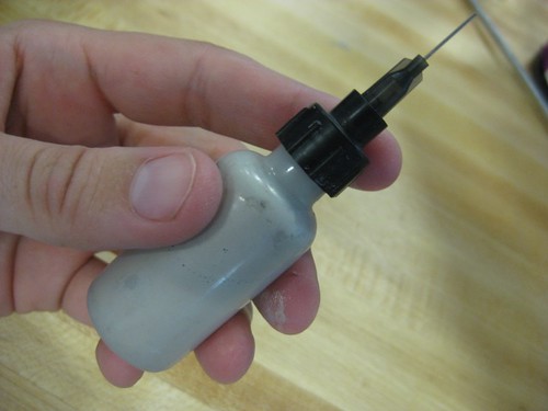
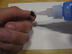
We have found it convenient to apply the copper conductive paint from squeeze bottles with very small nozzles. This allows us to paint very thin traces that can lead right up to the legs of the surface mount and through-hole components. it also gives the trace extra volume, thus better conductivity. which would otherwise have to be achieved by painting multiple layers of trace with a paintbrush.
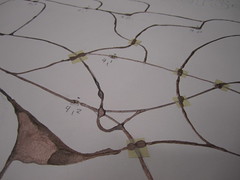
Since the paint oxidizes relatively quickly (within a day). When copper oxidizes it turns green.
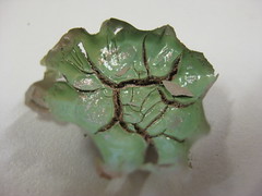
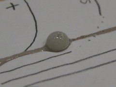
It is important to make sure the paint you are working with is kept fresh. Keep the paint sealed as airtight as possible. One trick is to add water to the paint in the pot when you know you will not be using it for a day or more.,This will create an air-tight layer over the surface of the paint. Be sure to pour this water away before you use the paint again.
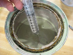
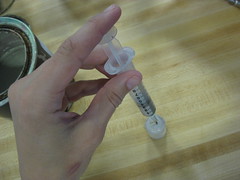
Stir paint in the pot using a clean stick until its consistency is even. Use a syringe to transfer paint from the pot to a squeeze bottle. depending on the size of traces you want, choose a nozzle of the appropriate size. For the traces in this example we used a 22 gage syringe cap nozzle. Which is less than 1 mm in diameter.
While painting use needle or stripped magnet wire to cork the nozzle when not in use. This will keep the nozzle from clogging.
Design your circuit
The great thing about painting a circuit is that you don’t have to draw straight, even or small traces. Take a look at the datasheet of your microcontroller and plan the layout of your circuit. You can use a pencil to sketch this layout on the sheet of paper you are going to use. You can plan to jump traces. You will do this by painting one trace first, then waiting for it to dry before sticking a sticker over it (creating a bridge) and drawing the crossing trace on top of the sticker.
Unless you program the microcontroller before mounting it, you will have to include traces for programming. These are:
* power (+)
* ground (-)
* SCK (serial clock)
* MISO (master in slave out)
* MOSI (master out slave in)
* RST (reset)
The code we use for the Paper Piano will require you to connect:
* the resistive track for the piano keys to pin PB4
* the loudspeaker to PB1
* the LED light to PB0
* power to battery power
* ground to battery ground

Preparing components for surface mounting
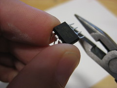
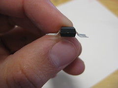
If you are working with components that are not surface mount you might have to adjust their connections, such as their legs, to stick out rather than down. Do this carefully with a pair of pliers or by bending them against a hard surface. Don’t bend the legs back and forth as they will become weak and fall off.
Super-gluing components to paper
If using a DIP (through-hole) microcontroller, bend its legs out so that the body of the chip can lie flat on a surface. Most surface mount components can be used as they are. Though sometimes the body might be slightly elevated over the legs and require some bending.
Put a small amount of superglue on the bottom side of the component (no need to put super glue on the legs of the component). Press the microcontroller onto the paper, and hold it in place until it sticks.

Drawing conductive traces
You will find it useful to have an extra sheet of practice paper lying around while you paint your circuit. Every time you begin drawing traces you will want to first draw a short trace on this scrap paper because often times the first amount of paint to come out will burst out and splatter, have bubbles or not come out at all.
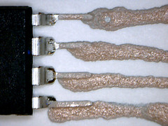
Start of drawing drawing practice traces and get used to regulating the amount of paint that comes out of the nozzle while you draw. to insure good connections between the paint and the component leg you want to cover the leg both on top and possible underneath, if there is some space. Use a multimeter to measure your connections.
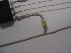
When you feel prepared, use the squeeze bottle to draw trace from the leg of each microcontroller (covering it somewhat) to wherever the trace should go.
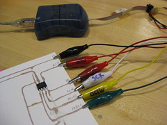
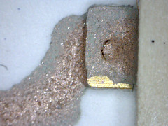
In order to program the microcontroler once it is mounted on the paper we draw conductive traces from the programming pins (see above) to the edge of the paper. At the edge of the paper you want a somewhat wider trace for attaching the alligator clip to.
Waiting for paint to dry
The copper paint will not turn conductive until it has tried. As it dries it will slowly become more conductive (it’s resistance decreases). For a single trace painted with the 22 gauge nozzle it takes about five minutes to dry enough to conduct for our purposes.
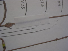
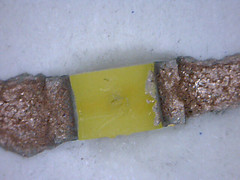
Jumping traces using stickers
When your traces are dry you can stick a sticker over them and then paint over the trace with the sticker as isolation in between.

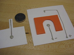
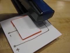
Paper battery holder
This is a design for a coin cell battery holder. It uses foam as a spacer (it is important that the foam is slightly thinner than the battery) with double-sided stickytape on either side. See images for design and construction.
Issues
Bubbles, connections…
Programming the microcontroller
In order to program the microcontroller mounted on the paper you need to make an adapter for your programmer that goes from the six female headers to six alligator clips. Use different colors and tags to name the alligator clips. You can now use the Arduino microcontroller programming platform to program ATtiny 85 and 45 chips, like the one used in this example. David Mellis has written a great tutorial on microcontroller programming here:
>> https://highlowtech.org/wiki/pmwiki.php?n=Main.ArduinoATtiny4585